


Connecting EMT Conduit to Junction Boxes: Installation Guide
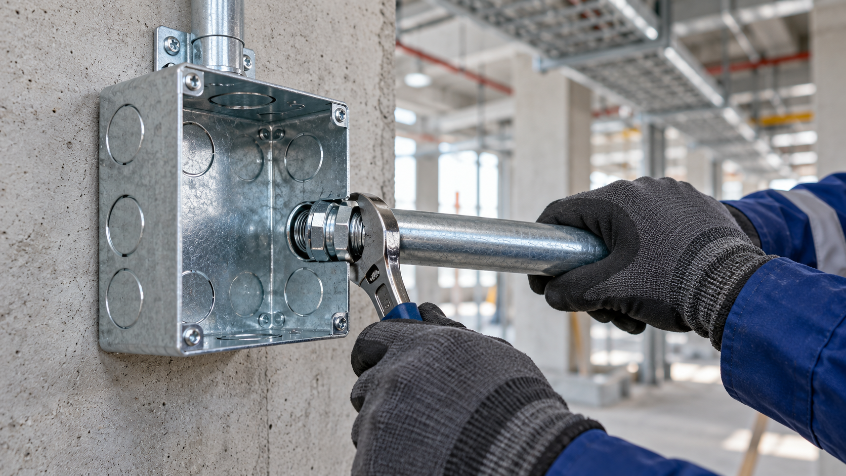
Connecting EMT conduit to a junction box requires correct coordination between the conduit size, box entry, connector, locknut, conductor arrangement and earthing system.
A poor connection can leave the conduit loose, damage conductor insulation or interrupt the electrical continuity of the metallic raceway. Selecting incompatible box entries and fittings can also lead to unnecessary drilling and modification on site.
This guide explains the general process of connecting EMT conduit to junction boxes and identifies the checks that MEP engineers, supervisors and electrical contractors should complete before installation on Saudi projects.
Electrical work should only be performed by qualified personnel in accordance with approved drawings, project requirements and applicable regulations. Circuits must be isolated and verified as de-energized before work begins.
What Is EMT Conduit?
EMT stands for Electrical Metallic Tubing. It is a metal raceway used to route and protect electrical conductors.
EMT conduit is commonly found in:
- Commercial buildings.
- Offices.
- Hospitals.
- Hotels.
- Warehouses.
- Service corridors.
- Plant rooms.
- Selected industrial installations.
- Exposed and concealed electrical systems where specified.
A complete EMT system can include:
- EMT tube.
- Connectors.
- Couplings.
- Bends or elbows.
- Saddles and clips.
- Junction boxes.
- Locknuts and bushings.
- Earthing and bonding components where required.
The system must be installed as a coordinated assembly. Selecting the correct conduit but using an incompatible connector or box entry can compromise the installation.
What Is a Junction Box Used For?
A junction box provides a protected and accessible location for conductors to be:
- Joined.
- Branched.
- Terminated.
- Redirected.
- Connected using approved terminals or connectors.
The junction box also provides entry points for the conduits serving the circuit.
If you are still choosing between available dimensions, review our junction box sizes guide before finalizing the installation.
A junction box should not be confused with a pull box. A pull box is primarily used to provide access while pulling conductors through long or complicated conduit runs.
Read our comparison of pull boxes vs junction boxes to understand which enclosure should be shown on the project drawings.
Components Required for an EMT-to-Junction-Box Connection
A typical connection may require:
- EMT conduit of the specified diameter.
- Compatible EMT connector.
- Junction box with a suitable factory entry or knockout.
- Locknut where required by the fitting design.
- Insulating bushing where required.
- Approved fastening components.
- Conduit supports or clips.
- Earthing or bonding components where required.
- Compatible box cover.
- Appropriate installation tools.
The connector must match both the conduit diameter and the box-entry size.
Do not attempt to compensate for a mismatched entry using improvised washers, excessive force or unsuitable sealants.
Types of EMT Connectors
Several connector designs may be used to terminate EMT conduit at an electrical box. The approved fitting depends on the project specification, location and installation conditions.
Set-screw EMT connectors
Set-screw connectors secure the conduit using one or more screws that tighten against the tubing.
They are commonly used in suitable indoor locations where the product and project requirements permit them.
The installer must ensure that:
- The conduit is fully inserted.
- The screw is tightened correctly.
- The connector body is secure.
- The conduit is not crushed or deformed.
- The connector matches the conduit diameter.
Compression EMT connectors
Compression connectors secure the conduit through a compression nut and internal ring or ferrule.
A correct installation requires:
- A clean, square conduit end.
- Full conduit insertion.
- Correct assembly of fitting components.
- Secure tightening.
- Compatibility with the box entry.
The connector’s environmental suitability must be confirmed from its product documentation. The word “compression” does not automatically establish an outdoor or liquid-tight rating.
Specialized connectors
Some projects may require fittings designed for specific applications or environmental conditions.
The engineer should verify:
- Product classification.
- Approved location.
- Material.
- Environmental rating.
- Compatibility with the conduit and box.
- Required certification or test documentation.
How to Connect EMT Conduit to a Junction Box
The following sequence provides general installation guidance. It does not replace the approved method statement or manufacturer instructions.
1. Review the Approved Drawings
Before starting, confirm:
- Conduit route.
- Junction-box location.
- Box dimensions.
- Conduit diameter.
- Number of entries.
- Entry direction.
- Connector type.
- Earthing requirements.
- Required box cover.
- Accessibility after finishing work.
The actual site conditions should be compared with the coordinated drawings before any box is drilled or fixed.
2. Select the Correct Junction Box
The box must provide sufficient space for:
- Incoming and outgoing conduits.
- Conductors.
- Connectors or terminals.
- Earthing conductors.
- Required bending space.
- Future inspection and maintenance.
Available Alrouf junction-box dimensions covered in our size guide include:
- 10 × 10 × 5.5 cm.
- 15 × 15 × 5.5 cm.
- 15 × 15 × 10 cm.
- 20 × 20 × 5.5 cm.
The box should be selected using its complete model code, not only its nominal length and width.
3. Confirm the Conduit and Knockout Sizes
Check that the box entry or knockout matches the selected EMT connector.
Confirm:
- Nominal conduit diameter.
- Connector thread or entry size.
- Knockout diameter.
- Available clearance around the entry.
- Position relative to other knockouts.
- Space required for the locknut and bushing.
- Required conductor direction inside the box.
A knockout that appears close in size may still be unsuitable for the selected fitting.
4. Mark the Required Entry
Use the coordinated conduit route to identify the correct box entry.
Choose an entry that:
- Maintains a direct conduit route where practical.
- Provides enough space between adjacent connectors.
- Avoids interference with the cover.
- Allows conductors to enter without sharp bends.
- Does not conflict with terminals or earthing points.
- Supports an organized internal conductor arrangement.
Do not remove unused knockouts.
5. Remove the Factory Knockout Carefully
Where a suitable factory knockout is provided, remove only the required section using an appropriate tool and method.
After removal:
- Check the opening for sharp edges.
- Remove loose metal fragments.
- Confirm that the surrounding box surface is not distorted.
- Verify the connector fits correctly.
- Ensure no debris remains inside the box.
Uncontrolled hammering can deform the box or damage adjacent knockouts.
6. Prepare the EMT Conduit
Measure the required conduit length after confirming the final positions of the box and supports.
The cut end should be:
- Square.
- Free from excessive deformation.
- Deburred.
- Clean internally and externally.
- Suitable for full insertion into the connector.
Burrs and sharp edges can damage conductor insulation during pulling.
After cutting, inspect the EMT carefully before connecting it to the box.
7. Install the EMT Connector
The exact process depends on the connector design.
A typical installation involves:
- Fitting the connector to the prepared conduit.
- Inserting the connector through the box entry.
- Installing the appropriate locknut or retaining component.
- Tightening the assembly using suitable tools.
- Checking mechanical security.
- Confirming that the fitting does not damage or deform the conduit.
- Installing a bushing where required by the design.
Follow the fitting manufacturer’s installation instructions and tightening requirements.
8. Align the Conduit
The conduit should enter the box without placing unnecessary stress on the connector.
Check that:
- The conduit is aligned with the box entry.
- The fitting is not carrying the weight of an unsupported conduit run.
- There is no visible distortion.
- Adjacent conduits have sufficient clearance.
- The route matches the coordinated drawing.
- The conduit can be supported correctly.
Do not force a misaligned conduit into the connector.
9. Support the EMT Conduit
Conduit supports should carry the conduit load and maintain the planned route.
Supports must be selected and positioned according to:
- Approved project requirements.
- Conduit size.
- Installation method.
- Supporting surface.
- Manufacturer guidance.
- Applicable regulations.
The junction-box connector should not be treated as the only support for the conduit.
10. Verify Earthing and Bonding
A metal junction box and metallic conduit system must be incorporated into the project’s earthing and bonding arrangement where required.
The installer should verify:
- Mechanical continuity at fittings.
- Correct use of earthing components.
- Secure earthing connections.
- Removal of paint or contamination where required by the approved method.
- Continuity across the complete system.
- Compatibility of all metal components.
Some box models may include a dedicated earthing point. The exact provision must be confirmed from the approved product documentation.
Do not assume that physical contact alone provides the required electrical continuity.
11. Pull and Arrange the Conductors
Conductors should only be pulled after:
- The conduit route is complete.
- Boxes and supports are securely installed.
- Conduit interiors are clear.
- Sharp edges have been removed.
- Fittings are correctly installed.
- The route has passed the required inspection stage.
Inside the junction box:
- Avoid sharp conductor bends.
- Keep conductor insulation undamaged.
- Arrange connections neatly.
- Use approved terminals or connectors.
- Maintain required identification.
- Keep sufficient working length where required.
- Avoid overcrowding.
The number of conductors must not be determined only by whether they can physically fit into the box.
12. Inspect the Connection
Before installing the cover, check:
- Connector tightness.
- Conduit alignment.
- Support positions.
- Box security.
- Entry condition.
- Earthing and bonding.
- Conductor insulation.
- Terminal security.
- Internal cleanliness.
- Accessibility.
- Cover compatibility.
Record the inspection in accordance with the project’s quality procedures.
13. Install the Junction-Box Cover
Use the cover specified for the box model.
The cover should:
- Match the box dimensions.
- Align with the fixing holes.
- Close the opening completely.
- Be secured using the correct fasteners.
- Remain accessible where required.
- Suit the intended environment.
Do not force an incompatible cover into place or leave the box open after completing the work.
Common EMT-to-Junction-Box Arrangements
Single conduit entry
A single conduit enters the box and the conductors terminate or connect inside it.
Check that the entry position provides enough space for the intended connection.
Through connection
One conduit enters and another exits, usually from the opposite side.
The conductor arrangement may pass through the box or include connections, depending on the design.
Branch connection
One incoming conduit serves two or more outgoing routes.
This arrangement may require:
- More box space.
- Additional connectors.
- Careful conductor identification.
- More working clearance.
- A larger cover-access area.
Multiple-side entry
Conduits enter from different walls of the junction box.
The engineer and installer should check that fittings do not interfere with each other and that conductors can be arranged without sharp bends.
Bottom and side entry
This arrangement is common where the conduit route transitions between horizontal and vertical directions.
The box depth and fitting positions should be reviewed carefully.
EMT Conduit and Junction-Box Selection Table
| Installation condition | What to check |
|---|---|
| One conduit entering a compact junction point | Entry size, conductor space and cover access |
| Conduits entering opposite sides | Alignment and internal working space |
| Multiple branch conduits | Box dimensions and connector spacing |
| Large or deep connectors | Box depth and usable internal volume |
| Several side entries | Knockout positions and fitting interference |
| Exposed conduit route | Mechanical security and support |
| Humid or dusty location | Verified environmental suitability |
| Coastal project | Material and corrosion-protection documentation |
Choosing the Correct Junction-Box Size for EMT
A box should be evaluated using:
- Conduit diameter.
- Number of conduits.
- Conductor quantity.
- Conductor cross-sectional area.
- Entry direction.
- Connector size.
- Box depth.
- Terminal arrangement.
- Earthing requirements.
- Maintenance access.
For example, a 10×10 cm box may provide enough space for one compact application, while another arrangement using the same conduit size may require a 15×15 cm box because of the number or direction of entries.
Always compare the complete arrangement rather than applying one box size to every installation.
Should the Box Be Drilled on Site?
Factory-provided knockouts should be used where their sizes and positions suit the approved conduit arrangement.
Additional site-made openings may be required in some projects, but they should only be created using an approved method.
Improper drilling can:
- Leave sharp edges.
- Damage the protective finish.
- Distort the box wall.
- Produce an incorrectly sized entry.
- Reduce connector security.
- Create metal debris inside the enclosure.
- Affect environmental performance.
After an approved opening is made, its edges and protective treatment should be completed according to the project requirements.
Outdoor and Coastal Installations
Saudi projects in Dammam, Khobar, Jubail and other coastal areas may be exposed to humidity and corrosive conditions.
For exposed installations, verify the complete assembly:
- Junction box.
- Cover.
- EMT conduit.
- Connectors.
- Locknuts.
- Bushings.
- Gaskets where applicable.
- Fasteners.
- Earthing components.
A galvanized finish alone does not confirm that the complete assembly is weatherproof.
Do not state or assume an IP rating unless the exact assembled product has supporting documentation.
Common Installation Mistakes
Avoid these frequent errors:
- Using the wrong connector size.
- Removing the wrong knockout.
- Leaving sharp edges on the conduit.
- Failing to deburr a cut EMT tube.
- Forcing misaligned conduit into the box.
- Using the connector as the only conduit support.
- Installing incompatible locknuts or bushings.
- Placing entries too close together.
- Overcrowding conductors.
- Ignoring box depth.
- Leaving unused openings unclosed.
- Failing to verify earthing continuity.
- Drilling the box without an approved method.
- Installing an incompatible cover.
- Concealing a junction box that must remain accessible.
- Claiming outdoor suitability without technical evidence.
Inspection Checklist
Before approving an EMT-to-junction-box installation, verify:
- Correct box model and dimensions.
- Correct EMT diameter.
- Compatible connector.
- Suitable entry or knockout.
- Clean and deburred conduit.
- Full conduit insertion.
- Secure connector and locknut.
- Correct conduit alignment.
- Approved supports.
- No damaged protective finish.
- No sharp edges.
- Correct conductor arrangement.
- Verified earthing and bonding.
- Compatible cover.
- Required accessibility.
- Compliance with approved drawings and method statements.
Frequently Asked Questions
How does EMT connect to a junction box?
EMT normally connects through a compatible EMT connector installed in a suitable box entry or factory knockout. The fitting may use a set-screw or compression design depending on the approved system.
Does the EMT connector need a locknut?
This depends on the connector design and installation method. Use the fitting components specified by the manufacturer and approved for the project.
Can I connect different EMT sizes to the same junction box?
Yes, when the box provides suitable entries and enough internal space for the complete conductor and fitting arrangement. Each connector must match its conduit and box entry.
Can I drill a junction box for an EMT connector?
Only where permitted by the project and completed using an approved method. Factory knockouts should be used where suitable.
Does EMT conduit need to be earthed?
Metallic conduit systems must be included in the required earthing and bonding arrangement. The exact method should follow the electrical design and applicable project requirements.
How do I select the correct junction-box size?
Consider the number and size of conduits, conductors, connectors, entry directions, depth and required working space. See the Alrouf junction box sizes guide for available documented dimensions.
Is a junction box the same as a pull box?
No. A junction box primarily contains connections or circuit branches, while a pull box primarily provides access for conductor pulling. Read the full pull box vs junction box comparison.
Can a standard galvanized junction box be used outdoors?
Not automatically. Outdoor suitability and any required IP rating must be verified from product-specific documentation for the complete assembled enclosure.
Conclusion
A reliable junction box EMT connection depends on selecting compatible components and installing them as a coordinated system.
Before installation, confirm:
- Junction-box dimensions.
- EMT conduit diameter.
- Connector type.
- Knockout or entry size.
- Conduit alignment.
- Support arrangement.
- Conductor space.
- Earthing and bonding.
- Cover compatibility.
- Environmental requirements.
The contractor should use approved drawings, manufacturer instructions and project procedures at every stage.
Alrouf Electrical Accessories provides documented steel junction-box and electrical-conduit product families for project requirements.
Contact Alrouf Electrical Accessories to request the current product catalogue and verified technical information for your EMT conduit and junction-box installation.


